SPI Protocol, Explained
Serial Peripheral Interface (SPI): the four wires (MOSI, MISO, SCK, CS), how a transaction works, its pros and cons versus I2C, and a simple Arduino example.
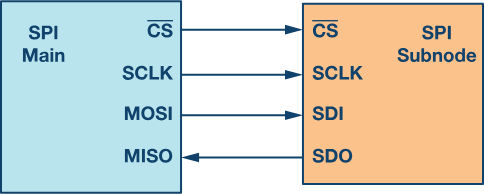
SPI stands for Serial Peripheral Interface, a way for electronic devices like microcontrollers to communicate with sensors or displays. One device (the master) sends a piece of data, the other device (the slave) sends a piece back, and they keep going until the message is complete. SPI uses four wires: MOSI, MISO, SCK, and CS.
- MOSI (Master Out Slave In): the wire the master uses to send information to the slave.
- MISO (Master In Slave Out): the wire the slave uses to send information back to the master.
- SCK (Serial Clock): the wire the master uses to send clock signals that synchronize the transfer.
- CS (Chip Select): the wire the master uses to select which slave it wants to talk to.
For communication, the master sends a series of bits over MOSI while sending clock pulses over SCK. The slave responds over MISO. Each transfer is a “transaction,” and multiple transactions can occur in a row as long as the master keeps CS low to keep the slave selected. Once done, the master raises CS to deselect that slave and can move to another.
Applications
- Memory devices: EEPROMs, Flash, and SRAM for reading and writing data.
- Sensors: accelerometers and temperature sensors.
- Displays: OLEDs and LEDs.
- Communication modules: Wi-Fi and Bluetooth modules.
- Motor control: communicating with motor drivers.
How to use it in Arduino
Arduino has built-in hardware support for SPI. On most boards the SPI pins are labelled MOSI, MISO, SCK, and SS (sometimes CS). SPI.begin() initializes the interface; digitalWrite(SS, LOW) selects the slave; SPI.transfer() sends and receives data; digitalWrite(SS, HIGH) deselects the slave.
Advantages of SPI
- Faster than asynchronous serial and I2C.
- No start and stop bits.
- No slave addressing mechanism like I2C.
- Full duplex: separate MISO and MOSI lines, so data can be sent and received at the same time.
- Not limited to 8-bit data.
- The slave hardware can be a simple shift register.
- Supports multiple slave devices.
Disadvantages of SPI
- Requires more wires than UART and I2C (which only need two lines).
- No acknowledgement to confirm data was received.
- No error-detection protocol.
- The master must control all communication (slaves cannot talk directly to each other).
- Usually needs a separate CS line per peripheral, which is awkward with many slaves.
- Supports only a single master.
- Suitable only for short distances.
Example Arduino code
#include <SPI.h>
int csPin = __;  // CS pin of the SPI device
void setup() {  SPI.begin();                  // Initialize SPI interface  pinMode(csPin, OUTPUT);       // Set CS pin as output  digitalWrite(csPin, HIGH);    // Deselect the device  Serial.begin(9600);}
void loop() {  digitalWrite(csPin, LOW);             // Select the device  SPI.transfer(0x55);                   // Send data to the device  int response = SPI.transfer(0x00);    // Receive data from the device  digitalWrite(csPin, HIGH);            // Deselect the device
  Serial.print("Response: ");  Serial.println(response);  delay(1000);}
Here the Arduino sends a byte (0x55) to an SPI device, reads a byte back, and prints it every second. You may need to adjust the SPI mode and clock speed for your specific device.
Originally published on sslabs.in.